Wires
Team: David GlockKai Magnus Müller Course: Interface Design Project date: Winter 2017Introduction
Section titled IntroductionThere is currently a wide range of tools available that make it very easy for users to create interactive prototypes starting with screen designs.
Development of projects that incorporate hardware - such as IoT projects - require specialized tools that are largely incompatible to existing design and prototyping workflows. Most tools are based in software development and focus less on UI design. If one wants to prototype IoT projects like Smart Home Apps, a lack of applications that connect both screens and hardware becomes apparent.
Current Approach
Section titled Current ApproachTo kick off our project we collected and analyzed a selection of existing prototyping software as well as hardware. Using our own experience 1, and reports of other students we compiled the typical process of developing hardware projects.
From here on we created a sample project during which a Smart Home App connected to various weather sensors got ready for prototyping. We went through each step it took to create a working prototype only using tools that are currently available collected difficulties and problems that arise in the process.

Existing Tools
Section titled Existing ToolsNext we analyzed a selection of prototyping tools and their features. Framer Studio, Principle and Origami represent the three main ways to create prototypes. We collected their main features advantages and drawbacks and decided to drop Principle from future analysis because its timeline based prototypes are inherently not flexible enough.
Framer’s and Origami’s features were then categorized with the Kano model. Documentation, element grouping, shortcuts and a prototype preview proved to be essential features. Other important but not elemental features are separation of programming and screen design, shareable prototypes and code snippets.
Programming
Section titled ProgrammingWe based our decision whether the prototypes of our application should be patch based or written with classical code on the user groups we defined. While some students are more familiar with code based tools, the number of students who can profit from more and better guidance is greater. Implemented correctly, syntax errors are easier to spot when using patches and they give a better visual overview. With this in mind we decided to focus on a patch based system going forward.
With these insights and our sample project, we were able to gather the necessary features for our use case and the order in which they became relevant.
Wires
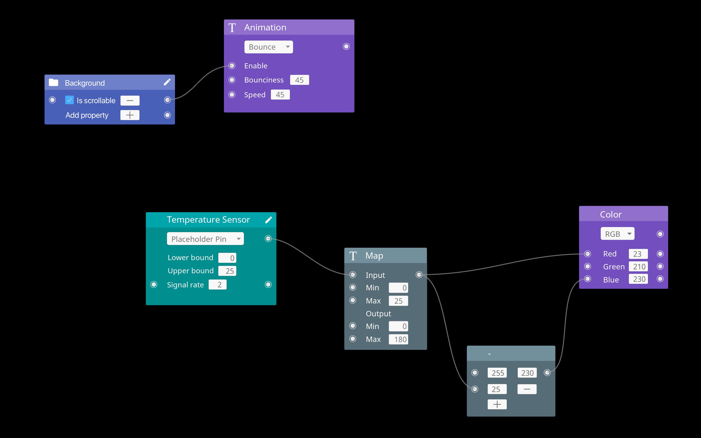
Section titled WiresOften times, the screen design is developed further than the hardware. To let users create prototypes despite no actual data coming in, Wires is able to generate placeholder data where sensor input would normally occur. This way the prototype can be simulated even when no hardware is actually present. All features are detailed in our sample use case below.
As a tool for productive use Wires is a native Mac App and uses standard macOS components. Main view is a canvas in the middle where patches are arranged and connected. In the left sidebar all imported screen designs are listed and available for use. The right sidebar includes output of selected elements and the prototype live preview.
Patches can be placed by searching and clicking the '+' button that appears. Layer patches can also be created by clicking the 'add' button next to a layer in the sidebar. The search gives a preview of the patches' in- and outputs and a brief description. Patches can have many different elements from simple text fields to checkboxes.
Patches
Section titled PatchesProperties can be added to patches via a plus button. Values can be set manually or are variable via their text field or with a connected input source respectively. When the placeholder pin is set on Arduino patches, the patch itself will generate random values between the set bounds and the current signal rate. This approach combines multiple patches in one to simplify the development process while leaving it open to custom solutions.

Process and Technology
Section titled Process and TechnologyFocus of this project was twofold. First, analysis of tools, workflows and users and second the synthesis of all findings into a new and improved Application.
My focus on this project was tool analysis, layout, structure of patches and their behavior. To present our final application I created the interactive part of our prototype to showcase the patches and their behavior with node.js. David Glock animated the rest of our features in After Effects. Both parts were then combined to form a seamless interactive and animated prototype.
About
Section titled AboutThis was a student project created during winter semester 2017/18 as part of the Interface Design I course by Fabian Gronbach together with David Glock.
Get the Documentation (.pdf, 16MB)
Footnotes
Section titled Footnotes-
We used the projects Feedback for Gesture Controlled Devices and Aral Sea - A Chronicle as a starting point for our analysis. ↩